Installing and Controlling Thermo
Scientific Devices
![]() Thermo Scientific Accela System: Hardware Synchronization with Accela
Autosampler
Thermo Scientific Accela System: Hardware Synchronization with Accela
Autosampler
![]() Note:
Note:
Support of the Accela system synchronisation is available starting with the SR11 Driver Update that provides extended Accela system support.
When an Accela system with an Accela Autosampler is used without any third-party modules, the synchronization of the pump, the autosampler and the detector can be performed per hardware synchronization using the Thermo Scientific System Interconnect Cable. This topic describes the prerequisites and restrictions of such a system setup, as well as how to set up and install the system.
Hardware
Options |
The system may include the following modules:
Note that it is not allowed to add other third-party modules to the same timebase. |
Restrictions:
|
In addition to the restrictions for each Accela module driver,
|
What is required?
Connection: |
Two free Ethernet ports and one free USB port and the following cables are required:
-or-
|
Hardware Installation
Connect
the autosampler and detector to an Ethernet switch or hub using the
Ethernet LAN cable shipped with the module and set the rotary switches.
For details how to connect modules via LAN and the required cables,
refer to ![]() Thermo Scientific Accela Autosampler
and PDA: LAN Connection.
Thermo Scientific Accela Autosampler
and PDA: LAN Connection.
Use a standard USB cable to connect the pump to the IPC.
Connect the Thermo Scientific System Interconnect Cable to each module as described in the hardware manual for the Accela Autosampler.
![]() Tip:
Tip:
For Thermo Scientific Accela hardware manuals, go to www.thermofisher.com. You will find the Manuals section under Service & Support.
Software Installation
In the Chromeleon Server
Configuration, add the Accela Autosampler,
Accela Pump, and Accela
PDA Driver
to a timebase. For details, see ![]() Adding, Configuring or Deleting Devices.
After you add the driver to the timebase, the Configuration dialog
or wizard opens automatically.
Adding, Configuring or Deleting Devices.
After you add the driver to the timebase, the Configuration dialog
or wizard opens automatically.
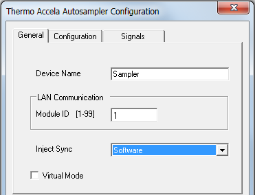
On the General tab page of the Accela Autosampler, specify the following settings:
Select
the Module ID which is
required to specify the network IP address of the autosampler.
The IP address is in the format 172.16.xx.111, whereby 'xx' corresponds
to the module ID of the autosampler.
Note: The module ID must match the rotary switch settings
at the rear panel of the autosampler. If you need to change the
switch settings, refer to ![]() Thermo Scientific Accela Autosampler
and PDA: LAN Connection.
Thermo Scientific Accela Autosampler
and PDA: LAN Connection.
Under Inject Sync , select Software.
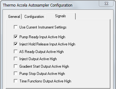
On the Signals tab page of the Accela Autosampler, select the Pump Ready Input Active High and Injection Hold Release Input Active High check boxes.
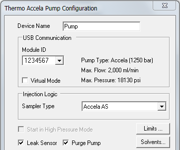
On the Configuration tab page of the Accela Pump, specify the following settings:
Select the Module ID (USB adress) of the pump.
Under Injection Logic, select Accela AS.
Choose the installed pump options.
On the General tab page of the Accela PDA, in the IP box, specify the Ethernet address for the instrument. The IP address is in the following format:
172.16.xx.162
whereby 'xx' must correspond with the module
ID value set by the rotary switches at the rear panel of the detector.
If you need to change the switch settings, refer to ![]() Thermo Scientific Accela Autosampler
and PDA: LAN Connection.
Thermo Scientific Accela Autosampler
and PDA: LAN Connection.
On the remaining tab pages, specify settings as required.
For information about the settings on a page, click the Help button or press F1.
Further Information
For detailed installation instructions, refer to the Accela hardware manuals.
![]() Troubleshooting for USB and TCP/IP Connections
Troubleshooting for USB and TCP/IP Connections
![]() Thermo Scientific - for an overview
of the different Thermo Scientific/Thermo Finnigan/ThermoQuest/TSP instruments
that can be controlled by Chromeleon.
Thermo Scientific - for an overview
of the different Thermo Scientific/Thermo Finnigan/ThermoQuest/TSP instruments
that can be controlled by Chromeleon.