Installing Dionex Devices
![]() ICS-Series Photodiode Array Detector: Installation
ICS-Series Photodiode Array Detector: Installation
Hardware Installation
|
Device Connection: |
Dionex strongly recommends installing Chromeleon software before connecting the detector to the Chromeleon server PC.
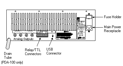
Fig.: Rear panel USB Port Connect the detector to the Server PC via the USB port on the rear panel. To do so, select one of the following methods:
|
|
|
Relay/TTL Control
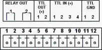
The PDA Ship Kit includes a 12-pin connector for relay and TTL connections. To attach individual wires and twisted pairs to the connector, strip the end of the wire(s), insert it into the connector, and tighten the locking screw(s) with a screwdriver. For information about the pin assignment for relay and TTL connections, refer to the table below: Pin Assignment Input Pin Function 1 Relay 1 output Active 2 Relay 1 output GND 3 Relay 2 output Active 4 Relay 2 output GND 5 TTL 1 output Active 6 TTL 2 output Active 7 TTL 1 input Active Autozero 8 TTL 2 input Active Reserved 9 TTL 3 input Active UV lamp on/off 10 TTL 4 input Active VIS lamp on/off 11 TTL input or output GND 1 12 TTL input or output GND 2
Connections 1 and 2 can be configured in Chromeleon to switch any low-voltage control. The switched current must be less than 200 mA and 42 V peak. |
|
Device Settings: |
No special settings required. |
|
Restrictions: |
Only two Photodiode Array Detectors are permitted on one server PC. |
Software Installation
Install the Device Driver in the Chromeleon Server Configuration. (For more information about the program, refer to Software Installation and Communication ![]() The Server Configuration Program.)
The Server Configuration Program.)
Start the Chromeleon server.
Start the Chromeleon Server Configuration program.
Add the detector to the timebase. Select Add Device on the Edit or context menu, and then select Dionex from the Manufacturers list box and PDA Photodiode Array Detector from the Devices list box.
The following settings are required:
On the General tab page, determine general instrument and hardware parameters, such as the installation name and the mode (live or virtual).
The Signals tab page indicates the signal assignment of the respective channels. Change the assignment only in exceptions.
On the State Devices tab page, verify that the check boxes for the installed relays/remote inputs are enabled.
The Error Levels tab page classifies the severity of any errors that occur. It is generally not necessary to change the default settings.
On the Demo Chromatogram tab page, select a demo chromatogram to display when acquiring data in Demo Mode.
On the Calibration tab page, enable/disable calibration functions for an instrument and set reminders for individual functions.
On the Diagnostics tab page, you may enable or disable the diagnostic functions for an instrument.
To control the detector, select a suitable Control Panel from the Dionex Templates\Panels\Dionex_IC folder in the Browser and connect the panel in the Chromeleon client to the corresponding timebase. As an alternative, use panel tabsets (refer to How to: ![]() Controlling Devices from the Panel Tabset in the User Help section).
Controlling Devices from the Panel Tabset in the User Help section).
Application
The User Help section provides an overview of the commands that are supported for the detector; refer to Commands for Controlling Dionex Devices ![]() Dionex Detectors and
Dionex Detectors and ![]() Dionex PDA/PDA-100/PDA-3000 Photodiode Array Detector.
Dionex PDA/PDA-100/PDA-3000 Photodiode Array Detector.
For different program examples for the detector, refer to Practical Tips for Device Control ![]() Detector Control in the User Help section.
Detector Control in the User Help section.
Troubleshooting
For a list of all error messages that may appear in Chromeleon, see the Error Levels tab page in the Server Configuration program.
Further Information
![]() Tip:
Tip:
For detailed installation instructions, refer to the ICS-Series Photodiode Array Detector Operator’s Manual.
For an overview of the detector, see ![]() ICS-Series Photodiode Array Detector: Overview.
ICS-Series Photodiode Array Detector: Overview.
For an overview of the different Dionex devices that are distributed at present, see ![]() Installing Dionex Devices.
Installing Dionex Devices.