Installing and Controlling Thermo
Scientific Devices
![]() Thermo Scientific TriPlus RSH/100 LS Autosampler: Clone and Dual Operation
Modes
Thermo Scientific TriPlus RSH/100 LS Autosampler: Clone and Dual Operation
Modes
Both the TriPlus RSH and the TriPlus 100 LS autosampler allow alternate injections into up to 4 inlets and on two separate GCs. This topic describes the hardware components required, how to establish connections, and how to set up the autosampler in the Chromeleon Server Configuration program.
What is required?
License: |
Two licenses Timebase Class 1 |
Connection: |
Autosampler: The autosampler can only be connected via Local Area Network (LAN). A free LAN port and cable are required for connection of the autosampler:
The IP addresses assigned to the instrument(s) must be fixed (permanently assigned)addresses. If you intend to connect your system to your site’s network, each piece of equipment must have a unique, fixed (static) IP address assigned to it.
Gas Chromatograph: Depending on the connection type of the GC (Ethernet (LAN) or serial (RS-232) communication), the following items are required for connection of a GC: Ethernet (LAN): A free Ethernet port and the following cables are required:
RS-232:
If the PC has a 25-pin COM port, an adapter cable is required for each port used (part no. 8914.0149). For more information refer to
|
Modules: |
–OR–
|
Installation in the Chromeleon Server Configuration
The section below describes the settings in the Chromeleon Server Configuration for two different use cases.
Installation with two GCs for injections into two inlets:
This configuration requires two physically separate GCs and one TriPlus RSH or TriPlus 100 LS autosampler. The sampler alternately injects into one inlet on each GC.
Create two timebases, one for each individual GC instrument. If you are using two TRACE 1300 GC, for example, you may create a "TRACE1300_01" (for the main autosampler device) and "TRACE1300_02" timebase (for the second (virtual) autosampler device).
Configure the first timebase ("TRACE1300_01"):
Add
the first GC and a TriPlus RSH (or TriPlus 100 LS) autosampler to
the timebase (see ![]() Adding, Configuring or Deleting Devices).
Adding, Configuring or Deleting Devices).
Configure the autosampler device: Open the Configuration page of the autosampler. Click the arrow in the Instruments drop-down list box and then click Main.
Configure the second timebase ("TRACE1300_02"):
Add the second GC and a TriPlus RSH (or a TriPlus 100 LS) autosampler to the timebase.
Configure the second (virtual) autosampler device: Open the Configuration page of the autosampler. Click the arrow in the Instruments drop-down list box and then click Virtual (Secondary). This will add the autosampler device as a virtual device on the second timebase.
The configuration would now look like this:
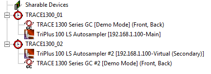
![]() Notes:
Notes:
In the example configuration above, the timebases include the same GC model. However, you may of course also use two different GC types in your configuration.
The Main/Virtual function can only be used in GC Liquids mode. In case of a TriPlus RSH in GC Headspace or SPME mode, the Virtual function is not supported.
Installation with two GCs for injections into 4 inlets:
This use case also requires two physically separate GCs and one TriPlus RSH or TriPlus LS 100 autosampler. Since each GC has to be shared between two timebases, make sure that both GCs support dual operation.
The difference as compared to the setting above is that the injections take place in four inlets instead of two.
In the example configuration below, a TRACE 1300 Series GC, a TRACE GC and one TriPlus RSH autosampler is used. Configure the system as follows:
Create 4 timebases, one for each inlet (named GC_TRACE 1300_Front Inlet, GC_TRACE 1300_Back Inlet, GC_Trace_Right Inlet and GC_Trace_Left Inlet in the example configuration below).
First timebase (here:
GC_TRACE 1300_Front Inlet): Add
the first GC to the timebase. For
instructions on adding devices to a timebase see ![]() Adding, Configuring or Deleting Devices.
Adding, Configuring or Deleting Devices.
Configure the first GC for dual operation: on the Timebase tab page, click the arrow in the Front Timebase list box and select GC_TRACE 1300_Front Inlet as the front timebase. Then click the arrow in the Back Timebase list box and select GC_TRACE 1300_Back Inlet as the back timebase.
Add the autosampler to timebase GC_TRACE 1300_Front Inlet.
Configure the autosampler device: Open the Configuration page of the autosampler. Click the arrow in the Instruments drop-down list box and then click Main.
Second timebase (here: GC_TRACE 1300_Back Inlet): This timebase already includes an instance of the first GC (that was added
Add the second instance of the autosampler to the second timebase .
Configure the autosampler device: Open the Configuration page of the autosampler. Click the arrow in the Instruments drop-down list box and then click Virtual (Secondary). This will add the autosampler device as a virtual device on the second timebase.
Third timebase (here: GC_Trace_Right Inlet): Add the second GC to the third timebase .
Configure the second GC for dual operation: on the Timebase tab page, click the arrow in the Assign Left Part to Timebase list box and select GC_Trace_Left Inlet as the left timebase. Then click the arrow in the Assign Right Part to Timebase list box and select GC_Trace_Right Inlet as the right timebase.
Add a Remote Inject driver to the timebase. On the General tab page, under Inject Port, select the appropriate GC injector.
Fourth timebase (here: GC_Trace_Left Inlet): Add a Remote Inject driver to the timebase. On the General tab page, under Inject Port, select the appropriate GC injector.
The configuration would now look like this:
 Tip:
Tip:
For information about configuration settings
for the Double Pro mode (injection into two different inlets on the same
GC), refer to ![]() Thermo Scientific TRACE 1300 Series GC: Dual Operation.
Thermo Scientific TRACE 1300 Series GC: Dual Operation.
Hardware Connection
Connect the autosampler to the GC by using the Y-shaped cable provided with the autosampler:
On the rear of the control interface of the autosampler, connect the main connector to the connection marked INTERFACE.
On the rear panel of the first GC, connect the first branch of the Y-cable, labelled GC 1, to the connector (On the TRACE 1300 Series GC II the connector is marked AUTOSAMPLER HANDSHAKE, on the TRACE GC it is marked AUTOSAMPLER SIGNALS, on the FOCUS Gas Chromatograph it is marked SAMPLER SIGNALS).
On the rear panel of the second GC, connect the second branch of the Y-cable, labelled GC 2, to the connector (On the TRACE 1300 Series GC II the connector is marked AUTOSAMPLER HANDSHAKE, on the TRACE GC it is marked AUTOSAMPLER SIGNALS, on the FOCUS Gas Chromatograph it is marked SAMPLER SIGNALS).
For more information about the Clone Mode also refer to the Operating Manual.
For information about the configuration settings on the other tab page, refer to:
![]() Thermo Scientific TriPlus RSH Autosampler: Installation.
Thermo Scientific TriPlus RSH Autosampler: Installation.
![]() Thermo Scientific TriPlus 100 LS Autosampler: Installation.
Thermo Scientific TriPlus 100 LS Autosampler: Installation.