Integral Process Analytical System Control
![]() SP2 Flow Path and Valve Control (Dilution)
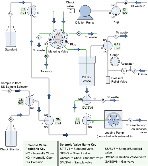
SP2 Flow Path and Valve Control (Dilution)
The diagram below shows the flow path through the components installed in an SP2. The table below the diagram lists the SP2 valves and the function each valve performs.
![]() Note:
Note:
When a solenoid valve is off, port NO is open and port NC is closed. When a solenoid valve is on, port NO is closed and port NC is open.
|
Valve |
Function |
|
SP_Solenoid_1 (SV1) |
On—directs stock standard to metering valve (for calibration standard preparation) |
|
SP_Solenoid_2 (SV2) |
On—directs diluent to dilution pump |
|
SP_Solenoid_3 (SV3) |
On—directs check standard to sample valve |
|
SP_Solenoid_4 (SV4) |
On—directs sample or check standard to ST valve |
|
SP_Solenoid_5 (SV5) |
On—directs diluted sample or calibration standard to loading pump |
|
SP_Solenoid_6 (SV6) |
On—directs diluted sample/standard to SS valve |
|
SP_Solenoid_7 (SV7) |
not installed |
|
SP_Solenoid_8 (SV8) |
On—pressurizes the dilution vessel |
|
SP_Solenoid_9 |
On—turns on the loading pump Note: To control the loading pump, SP_Solenoid_9 must be in Device Control mode. To select Device Control mode, start the Server Configuration program, open the Properties dialog box for the SP, and select the Solenoids tab. |
|
RotaryValve_1 |
Position 10–1—delivers diluent and loop contents to dilution vessel Position 1–2— loads sample or standard into the loop for delivery to dilution vessel |
Also, refer to
![]() Integral Process Analytical System Control
Integral Process Analytical System Control
![]() SP Sample Preparation Options
SP Sample Preparation Options