Creating and Modifying Programs
![]() Defining an Inverse Gradient (UltiMate 3000 DGP-3600RS/SD/BM)
Defining an Inverse Gradient (UltiMate 3000 DGP-3600RS/SD/BM)
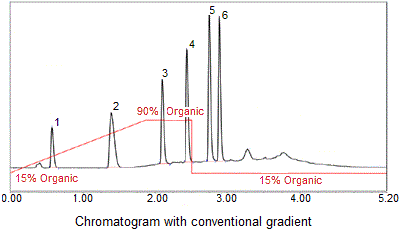
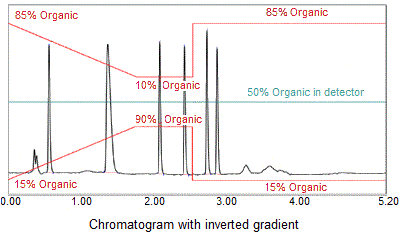
With the Invert function provided in the Chromeleon PGM Editor it is possible to perform a gradient compensation when using a dual UltiMate 3000 DGP-3600RS, SD or BM pump in a gradient program. During gradient compensation, an inverse of the analytical gradient of the right pump is created and applied to the flow of the left pump. The flow of the analytical gradient is then mixed with the flow of the inverted gradient after the column, but before the detector, thus yielding a constant composition of the mobile phase.
The procedure is especially suitable for nebulizer-based detectors, such as the Corona ultra or Corona RS, as the typical variations in response caused by the varying composition of the mobile phase are compensated. Thus, the benefits of nebulizer-based detectors can now be used also for gradient elution.


A dedicated Viper™ Kit (Inverse Gradient Kit for Uniform Response, Dionex p/n 6040.2819 or 6040.2820) is also available to establish the required fluidic connections. Make sure to follow the kit's installation instructions (Inverse Gradient for Uniform Response - Quick Installation Guide) for setting up the system to ensure correct assignment of the PumpRight and PumpLeft functions.
After establishing the fluidic connections, do the following to create a program with an inverted gradient:
Create a Programm using the ![]() Programm Wizard.
Programm Wizard.
On the File menu, select New.
Select Program File from the list box.
Select the timebase in which the system is installed. Follow the wizard and enter the required information in the input fields on the corresponding wizard pages.
On the PumpRight Options page, select Multi-Step Gradient from the Gradient Type list box.
On the Flow Gradient PumpRight page, specify the settings for the flow rate and the %-Gradient. Make sure that the flow rate remains constant during the run of the program. Otherwise, it is not possible to create an inverse gradient.
![]() Tip:
Tip:
It is not necessary to specify the settings for the left pump, as the inverted gradient profile for this pump will later automatically be generated in the PGM Editor.
Continue specifying the settings on the remaining wizard pages. If you need help, press the F1 key. After completion of the program, the PGM Editor is launched. Go to the Device View for the left pump.
On the Flow page, select the Multi-Step Gradient type. This enables the related page of the PGM Editor.
On the Multi-Step Gradient page click the Invert button to specify a delay time for the flow of the inverted gradient of the left pump. The delay time is used to compensate for the time it takes the flow of the analytical gradient ('PumpRight') to pass the column and reach the detector. By default, the value is set to 0, that is, no delay time is calculated.
Click OK to enable inversion of the gradient.
Repeat steps 4–9 for each new analytical gradient or after modification of an existing gradient.
–or–
Repeat steps 8 and 9 to invert the same analytical gradient several times in a program.