Installing Special Drivers
![]() Virtual Channel Driver (VCD): Configuring the Channels of the Virtual Channel Driver
Virtual Channel Driver (VCD): Configuring the Channels of the Virtual Channel Driver
The Chromeleon Virtual Channel Driver (VCD) needs to know the expressions to be recorded. Which channels are used with which properties is defined in the Program (see ![]() Program Examples for Virtual Channels). Thus, you can use separate settings for each sample, sequence, or batch.
Program Examples for Virtual Channels). Thus, you can use separate settings for each sample, sequence, or batch.
To determine the channel type
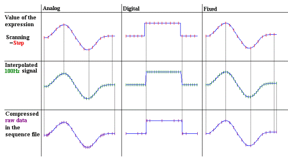
To optimize the signal recording, you can define the type for each virtual channel during installation. The defined channel type will be used as a default in the Program Wizard. Three types are available:
|
Analog |
Suitable for expressions that a) change quickly, such as pump pressure, and/or b) consist of other analog signals |
Examples: Formula = a) Pump.pressure b) UV_VIS_1/UV_VIS_2 |
|
Digital |
Suitable for digital expressions, such as the state of relays |
Relay_1.State AND Relay_2.State |
|
Fixed |
Suitable for expressions that change slowly |
Pump.%A |
![]() Tip:
Tip:
If step gradients occur for virtual signals consisting of other signals even if the channel type is set to Analog, the resolution in y direction is insufficient. In this case, set FormulaMin/FomulaMax accordingl
The selected type affects the Step, MaxAutoStep, and Average settings of the corresponding signal and the selection of appropriate raw data compression. For the standard compressor, these three parameters have the same significance as with normal signal channels. For the step compressor, the values have no significance because this compressor always uses a fixed step of 0.01s. The default values are as follows:
|
|
Step |
MaxAutoStep |
Average |
Compression |
|
Analog |
Auto |
5.1s |
On |
Standard compressor |
|
Digital |
Fixed, 0.01s |
|
|
Special compressor for step signals |
|
Fixed |
Fixed, 0.01s |
5.1s |
Off |
Standard compressor |
For analog or fixed channels, you can change Step, MaxAutoStep, and Average values after you have selected the type. If these properties are set for digital channels, a warning appears.
For a better understanding and to avoid artifacts, refer to the schematic representation of different signal conversions below:

![]() Notes:
Notes:
The data acquisition step for digital signals is always 0.01s.
Step = Auto and Average = On is not considered for fixed channels.
To define the formula for the signal to record
Select Formula to specify the expression to be recorded. You can use the same expressions as for Trigger conditions, i.e., arithmetic and logical links. The expression must be numeric. During program execution, the FormulaCur property indicates the value calculated. FormulaMin and FormulaMax define the minimum and maximum signal values. If the measured signal exceeds the FormulaMax value, only the FormulaMax value is used for the data point. (This also applies to FormulaMin.)
![]() Note:
Note:
The more the measuring range is limited by FormulaMin and FormulaMax, the better is the signal resolution.
As for other signal channels, you can use the Value property to display the current (or interpolated) signal value (changes every 0.01s).
The Equate property allows you to enter a user-defined name for the virtual channel during the analysis. Use the Log command to include the name in the Audit Trail.
It is not possible to change the Step, MaxAutoStep, Average, Formula, and Type properties during data acquisition. The FormulaCur property is read-only and indicates the current value.