Generic Device Driver
![]() Range of Values, Truth Tables, and Value Sets
Range of Values, Truth Tables, and Value Sets
Frequently, specific parameters can only be modified using discrete steps or they can assume certain values only. Sometimes, it may be a good idea to assign meaningful terms to specific instrument states that are serially controlled via numerical parameters. For example, assign INJECT and LOAD to the motorized switching valve settings instead of 0 and 1. To enter settings, the Step and Table parameters are available for numerical values in the edit dialog box.
Discrete Equidistant Value Distributions
The default setting for Step is zero. As soon as this integer variable is larger than zero, it determines the number of equidistant steps for the range of values between Min and Max. The input 1 means that the values Min and Max are valid only. The input 2 enables Min, Max, and the value (Min+Max")/2, etc. Thus, Step is used to select a discrete quantity of valid input values from the progressive range of values between Min and Max. Neighboring values are divided by (Max-Min)/ Step. If the device driver receives numerical inputs for this parameter that do not correspond exactly to the discrete value, the input is automatically replaced by the nearest valid value. A corresponding message is included in the Audit Trail of the timebase.
Frequently, valid values are not equidistant or you do not only want to display the instrument status as numerical values. In this case, use the Table.
User-Defined Value Sets and Lists
Select Use Table to enable the table.
This action disables Type, Min, Max, Step, and Number of Digits controls for entering the parameter definition. The description of the discrete range of values is exclusively via the table. Two different modes are available. You can select them using the Enumerated and Numerical keys.
Example:
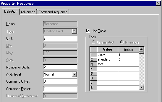
In a detector, the CTIME=X<CR><LF> command string shall control the Response time constant for the output signal. X can assume the numerical values 1, 2, and 3, which correspond to the instrument settings (slow, standard, and fast). To display the actual settings instead of the numbers, enable the Table and select the Enumerated mode. The column headers in the table are now Value and Enumerator. Enter the terms for the status description below Value and the corresponding numerical values in the Enumerator column. For this example, the input is as follows:

The settings slow, standard, and fast appear on the screen. These settings are converted into the command strings: CTIME=1<CR><LF>, CTIME=2<CR><LF> and CTIME=3<CR><LF> (if the selected format is CTIME=@d,Response@<CR><LF>).
The Numerical input mode selects discrete, non-equidistant values and their mapping to the corresponding control indices, respectively. This can be used, for example, for specifying amplification factors that are frequently adjustable in the 2, 5, 10 grid across several orders.
Example:
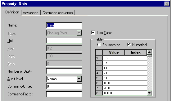
For the Gain variable, the values 0.2, 0.5, 1, 2, 5, 10, 20, 100 are valid only. The GAIN=@.1f,Gain@<CR><LF> command string communicates them to the instrument. X represents the current value.
Select the Numerical mode and enter the values in the Value column in ascending order.
The Index column remains empty.
Now, discrete values are valid only. If you enter deviating values that are still within the Min - Max range, the device driver changes them to the nearest valid values. The correction is also logged in the Audit Trail.

Indexed Discrete Value Sets
In addition, discrete values are frequently indexed, that is, each value is assigned an integer value. These values are entered in the Index column.
If you want to index discrete values, each value must receive a corresponding integer value in the Index column.
Within the command string, the integer value is used instead of the floating-point number. The device driver converts the values into the indices. Then, an integer format instruction such as d is used to send them to the instrument.
You can also use this feature to translate enumerated constants into ASCII characters. Enter the corresponding ASCII value as the index and use the format instruction c.
Example:
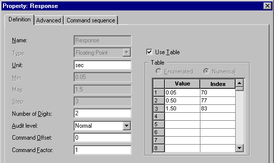
For the Response variable, the values 0.05, 0.5, and 1.50 are valid only. The RESPONSE=X<CR><LF> command string communicates them to the instrument. Depending on the value for the variable, X represents the letter F (ASCII 70), M (ASCII 77) or S (ASCII 83). Use the format RESPONSE=@c,Response@<CR><LF> and the following table:
