Installing and Controlling Third-Party
Devices
![]() Gilson 202 Fraction Collector (Ext.): Tray Configuration
Gilson 202 Fraction Collector (Ext.): Tray Configuration
In the Server Configuration program, select the Collector tab page of the Gilson 202 Fraction Collector (ext.) properties. Specify your tray configuration by selecting the Number of racks and the Type from the corresponding lists.
![]() Tip:
Tip:
When you install the racks, install the first rack in the leftmost position of the tray, and install additional racks adjacent to the first one.
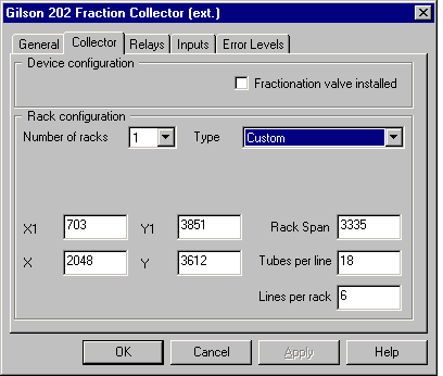
Usually, you will use predefined racks. However, if you select Custom as the rack type, you can specify the tube positions yourself:

The meaning of the fields is as follows:
Field |
Description |
X, Y |
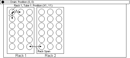
Distance between neighboring tubes in x or y direction. (Note: The distance in one direction must be identical.) |
X1, Y1 |
Position of the first tube in the first rack. |
Rack Span |
Distance between the last row of the first rack and the first row in the next rack. |
The position of the drain tube is the origin of the coordinate system. Thus, its coordinates are 0.0:

Coordinate input is in Gilson 202 unit steps. In x-direction, 65536 steps are 391 mm; in y-direction, they are 219.5 mm.
In addition, type the Tubes per line and the Lines per rack in the associated entry fields.
Further Information
For information about how to install the Gilson
202 Fraction Collector with the Gilson 202 Fraction Collector (ext.) device
driver, refer to ![]() Gilson
202 Fraction Collector (Ext.)/204 Fraction Collector: Installation.
Gilson
202 Fraction Collector (Ext.)/204 Fraction Collector: Installation.