Installing the Pump Control Card
![]() Pump Connection and Pin Assignment
Pump Connection and Pin Assignment
![]() Tips:
Tips:
Due to its obsolete technology, the pump control card is no longer available from Dionex. However, pump control cards may still be used in the field. Therefore, refer to the installation instructions below if necessary.
This card is not supported under Windows Vista or later.
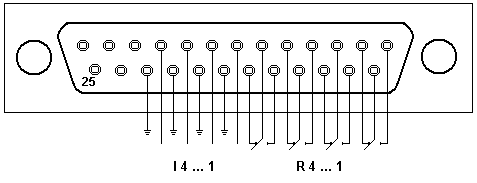
The relay output of the pump control card is located on a 25-pin SUB-D connector. Four remote inputs (I1 - I4) and four additional relays (R1 - R4) are available. For information about the pin assignment, refer to the picture below:

The maximum switching potential of the relays is 100 V with a contact rating of 10 W. Make sure that a maximum current of 0.5 A is not exceeded. To enable a response to external events, such as an Inject signal, the relay card is fitted with four remote inputs. They are enabled when a relay closing contact, e.g., of the autosampler, grounds the corresponding input signal.
The relay connections are located on the 25 Sub-D connector of the separate slot sheet. A ribbon cable is provided in the accessories kit.
|
Description |
Connector |
Ribbon |
|
Relay 1, normal open |
1 |
1 |
|
Relay 1, common |
14 |
2 |
|
Relay 1, normal closed |
2 |
3 |
|
Relay 2, normal open |
15 |
4 |
|
Relay 2, common |
3 |
5 |
|
Relay 2, normal closed |
16 |
6 |
|
Relay 3, normal open |
4 |
7 |
|
Relay 3, common |
17 |
8 |
|
Relay 3, normal closed |
5 |
9 |
|
Relay 4, normal open |
18 |
10 |
|
Relay 4, common |
6 |
11 |
|
Relay 4, normal closed |
19 |
12 |
|
Remote Input 1 |
7 |
13 |
|
GND |
20 |
14 |
|
Remote Input 2 |
8 |
15 |
|
GND |
21 |
16 |
|
Remote Input 3 |
9 |
17 |
|
GND |
22 |
18 |
|
Remote Input 4 |
10 |
19 |
|
GND |
23 |
20 |