Installing the A/D Converter Card
![]() Pin Assignment on the A/D Converter Connector/Cable Connection
Pin Assignment on the A/D Converter Connector/Cable Connection
![]() Tips:
Tips:
The A/D converter card is no longer available from Dionex. However, as A/D converter cards may still be used in the field, refer to the corresponding installation instructions below.
This card is not supported under Windows Vista or later.
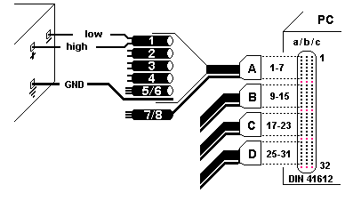
The A/D converter card is fitted with a common DIN 41612 connector (DIN = German Industry Standard). It has three vertical columns each comprising 32 contacts. The distance between the contacts is 0.1 inch. When you look at the contact pins of the connector from the computer's rear panel, the right column is column a, the middle column is column b, and the left column is column c. The upper contact corresponds to contact 1, the lower to contact 32.
|
|
c1 Channel 1 High c2 GND ... ... c15 Channel 8 High c16 GND c17 Channel 16 High c18 GND ... ... c31 Channel 9 High c32 GND |
b1 Channel 1 Dig. Inp. b2 GND ... ... b15 Channel 8 Dig.Inp. b16 GND b17 Channel 16 Dig.Inp. b18 GND ... ... b31 Channel 9 Dig.Inp. b32 GND |
a1 Channel 1 Low a2 GND ... ... a15 Channel 8 Low a16 GND a17 Channel 16 Low a18 GND ... ... a31 Channel 9 Low a32 GND
|
Connect the connector to the corresponding position with the cables pointing downward:

There are no fixed positions for the cables. Therefore, connect a single cable to the top position, that is, from channel 1 to 4. If required, additional cables can be connected below.
For example, to record a signal on channel 1, connect the positive pole (+) of the instrument with the wire "high" of channel 1, the negative pole (-) with the wire "low," and the A/D converter ground wire (GND) with the instrument ground.
The DIN 41612 connector on the A/D converter card provides 3 rows (a, b, and c) with 32 input pins each, allowing you to connect a maximum number of four A/D converter cables. One row of pins remains vacant between the connectors.
Four analog signals (1, 2, 3, and 4) and two times two digital signals (5/6 and 7/8) can be recorded via each cable (A, B, C, and D). Two Remote Inputs Dig.Inp1/2 share one ground connection (gnd).

After the A/D converter is connected, add the Dionex AD Converter as a Sharable Device. Then, the channels of the A/D converter are available for the installation of instruments with analog signal output.